Benefits of the Diagnosis on Medium and High Voltage Cables
All the underground electric networks, mainly the medium voltage ones, are exposed to be installed under bad conditions. Typically, most of the failures that take place in medium and high voltage networks are caused by the workforce incorrectly placing the cable in the duct or trench, problems on the installation of its accessories (Terminations and Joints) as well as the lack of qualified supervision during its installation.
For this reason, it is fundamental to test and diagnose the underground networks, as a vital opportunity to accurately evaluate and identify the present weak points in the distribution cables before putting them into service. Mainly, the insulation of the polymeric electric cables used in medium voltage, such as the XLPE and EPR are affected by the following instances:
- Growth of water tree structures. Under humidity, high temperatures, and strong electric fields, these microscopic structures grow deteriorating the insulation. It is worth to single out, that its growth rate is typically slow, and can last between 6 to 12 years to provoke a conversion into an electric tree structure and then generate a failure. Its evaluation is obtained through the measurement of the delta tangent or dissipation factor.
- Partial Discharges Activity due to the incorrect installation of joints and terminations, delaminating between insulation and semi conductors, cavities, or pollutants in the dielectric due to factory defects, as well as superficial damage on the semiconductor layer. A partial discharge is defined as an electric discharge located inside of the insulation. Different than water tree structure, the growth of a partial discharge is very fast and its conversion into failure can be imminent.
- Overloads in the conductor or circulatory currents on the screen that provoke thermal ruptures, typically caused by mistakes in the planning and dimensioning of the network.
Nowadays, cable manufacturers offer a great quality on the polyethylene extrusion, as well as dielectrics in excellent conditions, guaranteed through industrial frequency tests (50/60 Hz) with certified results of absence of partial discharges or values under 5pC, offering a useful life between 25 and 30 years.
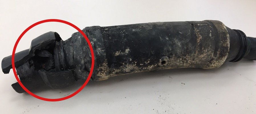
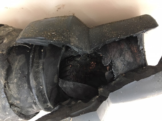
Many recent buried cable systems throughout the world have had failures in the first five years of operation. The majority and most common cause of these electrical service interruptions has been installation problems. Exceeded curvature radius in the installation, improper removal of the semiconductor, perforation of the insulation due to the inadequate use of tools, bad hot shrinked of the joint, use of incorrect size of connectors and pollutants left in the inside of accessories are only some of the typical problems.
Therefore, due to the need of high quality and reliability of the electric service, a Partial Discharge Diagnosis which allows identifying, measuring, and locating the presence of these problems is of vital importance. Let us see some examples of failures in the electric service, which could have been avoided if predictive diagnosis of Partial Discharges had been done.
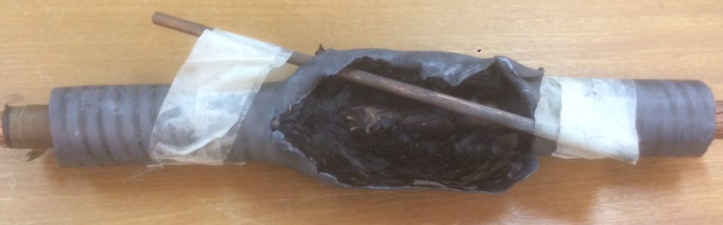
Picture 2 shows a Paper Insulated (PILC) lead covered cable pierced by a metal rod in the transverse direction of the insulation. This cable could have functioned several months under this condition before an interruption of the service would have taken place.
The pitting or erosion on the insulation, due to partial discharges activity will lead us to an immediate failure on the insulation of XLPE cables. However, we must take into consideration, there are insulating materials which are more resistant to partial discharges than others. For example, the terminal cups and joints have a great capacity to support partial discharges compared to the main insulation. It is common, that partial discharges exist in the cable accessories since they are installed by the man´s hands on field conditions. Therefore, it is very important to locate the partial discharge on the length of the cable to determine its severity degree.
Other important parameters to be determined in this measurement are the inception voltage (PDIV) and the extinction voltage (PDEV) of the partial discharge. The Inception Voltage of the Partial Discharge also known in literature as is defined as the voltage magnitude where the partial discharges due to cable defects and its accessories appear or start up. It is important to point out, that if its value is under the operation voltage (Uo), the defect conversion into a failure can happen in a relative short time, like in hours, weeks, or few months.
On the other hand, the Extinction Voltage of the Partial Discharge (PEDV) is defined as the magnitude of the applied voltage where the partial discharge turns off or extinguishes.
The same as when you evaluate the PDIV, in case that the PDEV is below the operation voltage (Uo) once a partial discharge is turned on, it will stay lit erosioning the insulation and producing an imminent failure.
The measurement of Partial Discharges on Cables based on the IEEE and IEC standards, are thoroughly recommended when doing quality acceptance withstand testing on new sections of cables, thanks to the ability to detect problems when installing before a failure is produced, as well as for predictive maintenance aiming to get a positive effect in the cost structure with respect to failure rates on the network, (Condition-based Maintenance).
In this sense, NDTector Inc. provides Portable Cable Tests and Diagnosis equipment, which allows obtaining very satisfactory results, due to its high technology, satisfactory results in the field even in high electric noise environments.
There are different sources of voltage for the measurement of partial discharges, like the ones generated from resounding equipments, VLF 0.1 Hz Sinusoid or Cosine Rectangular and Oscillating Wave DAC (Damped AC).
Many measurements, as well as the recommended IEEE 400.2-2013 indicate that VLF 0.1 Hz Sinusoid do not produce partial discharges compared to the ones that take place on the cable while in operation at 50/60 Hz, thus the sources VLF Rectangular Cosine and DAC Wave, are preferable since their pronounced gradients in the polarity change of the alternate wave produces comparable effects to the operation conditions hence a better and more exact measurement of partial discharges as to their PDIV and PDEV magnitude and location.
Listed below, there are some examples of field measurements made on a predictive manner on recently installed medium voltage cables, and on cables with long periods in operation.
Example 1. Cables VLF 0.1 Hz Cosine Rectangular at 3Uo Acceptance Withstand Test with cable partial discharges measurements XLPE 12/20 kV 650 meters.
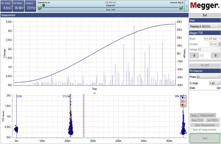
On this measurement it is worth mentioning, that the cable as well as the joint at 265 meters are free of partial discharges, different than the terminals and joints located at 200 meters.
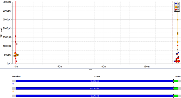
Example 2. Diagnosis of Partial Discharges with DAC source to a Mixed Cable 6/10 kV 185 meters. Cable and Joint are free of partial discharges, terminations show partial discharges presence.
Additionally, it is necessary to point out the benefits of the cable integral diagnosis through the Tangent Delta Measurement.
This diagnosis applies for PE/XLPE, EPR, and PILC Cables in order to determine the aging and deterioration of the cable insulating material, basically due to the humidity inside (water trees).
The result of this measurement based on the IEEE 400.2-2013 parameters, provides the operator with essential information about the reliability of the service section being tested.
This information is vital for the decision about repairing or replacement of the cable. The main problem with the cables with polyethylene insulation is the growth of water tree structures. Under the influence of humidity, high temperature, and strong electric fields, the length of these microscopic structures increases with the operation time and the subsequent conversion into an electrical treeing that can lead to a failure or an interruption of the cable segment.
The crucial decision of replacing only segments or the total length of the cable is based on technical information gathered with this test. It is obvious that this produces substantial economic savings.
NDTECTOR Inc., offers equipment and required personnel to perform underground electric cable evaluations through the measurement of Partial Discharges to verify the conditions of installation and manufacture of medium voltage cables, as well as the Measurement of the Tangent Delta to determine the aging state and prediction of its useful life.
This service inspection applies to:
Medium and High VoltageCables with PE/XLPE, EPR, and /or PILC insulation up to 230 kV.
Performance: Evaluation of 2 to 4 Circuits per day. (depending on the disposition and configuration of the installation).
Defects to Visualize:
- Partial Discharges: Terminals and Joints Installation problems, cavities and manufacturing defects on the cable insulation. Recommended techniques for recently installed cables. It also applies for aging cables.
- Tangent Delta: Humidity contents and Real Aging (Lifetime) of electric cables recommended technique for cables with many years in operation.
Test and Diagnosis System for Cables using Tangent Delta and Partial Discharges through VLF 0.1 Hz Sine, Cosine, Rectangular and/or DAC wave.
Report: The report will include the following:
- Blueprint of the Evaluated Cable.
- Time domain Reflectometer
- Cable Sheath Testing.
- Applied Wave Curve (VLF or DAC) for Partial Discharges.
- Calibration Curve of the Partial Discharge Measurement.
- Partial Discharges detected on the Cable, with PDIV and PDEV magnitude and location.
- Visualization of the partial discharge phase at the applied frequency.
- On the Tangent Delta measurement: Results chart with aging condition of the cables: Normal, Aged or Critical.
- Daily preliminary Reports.
- Final report with details of the inspection, conclusions, and recommendations as to replacement or maintenance of the cables five days after the inspection is finished.